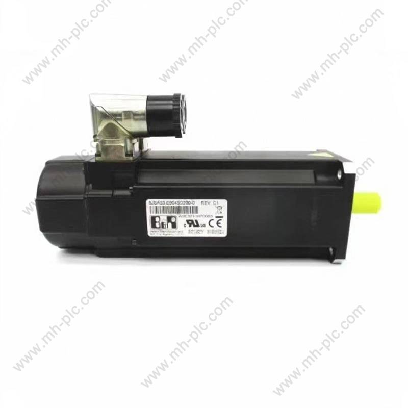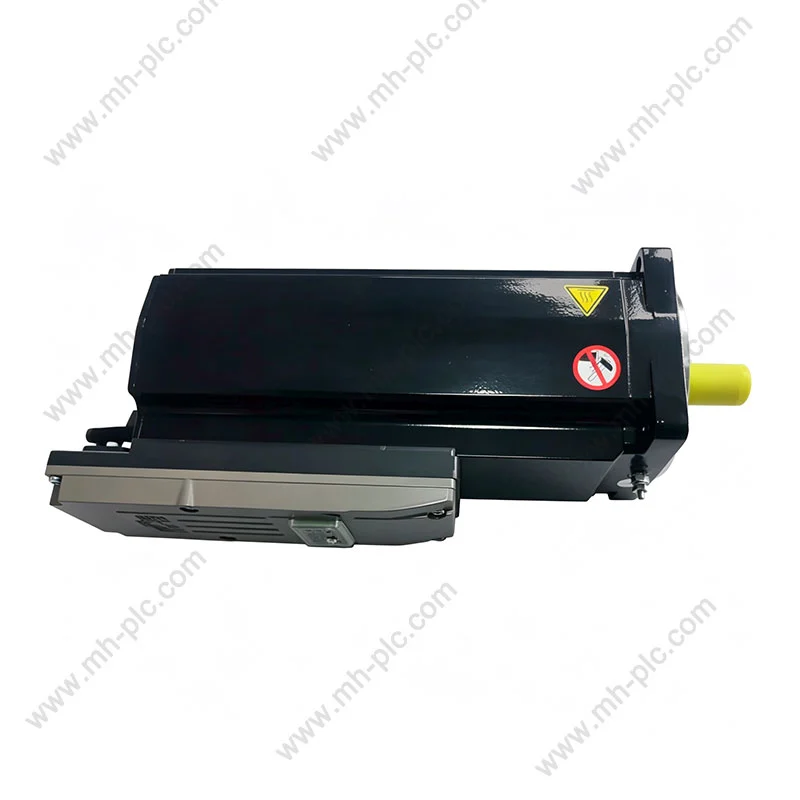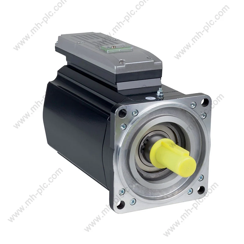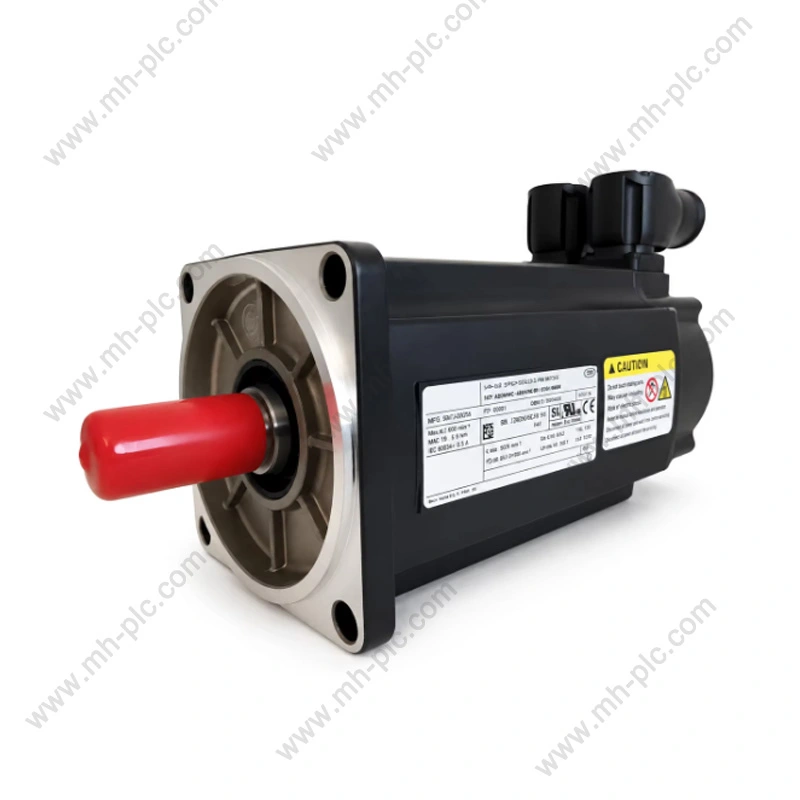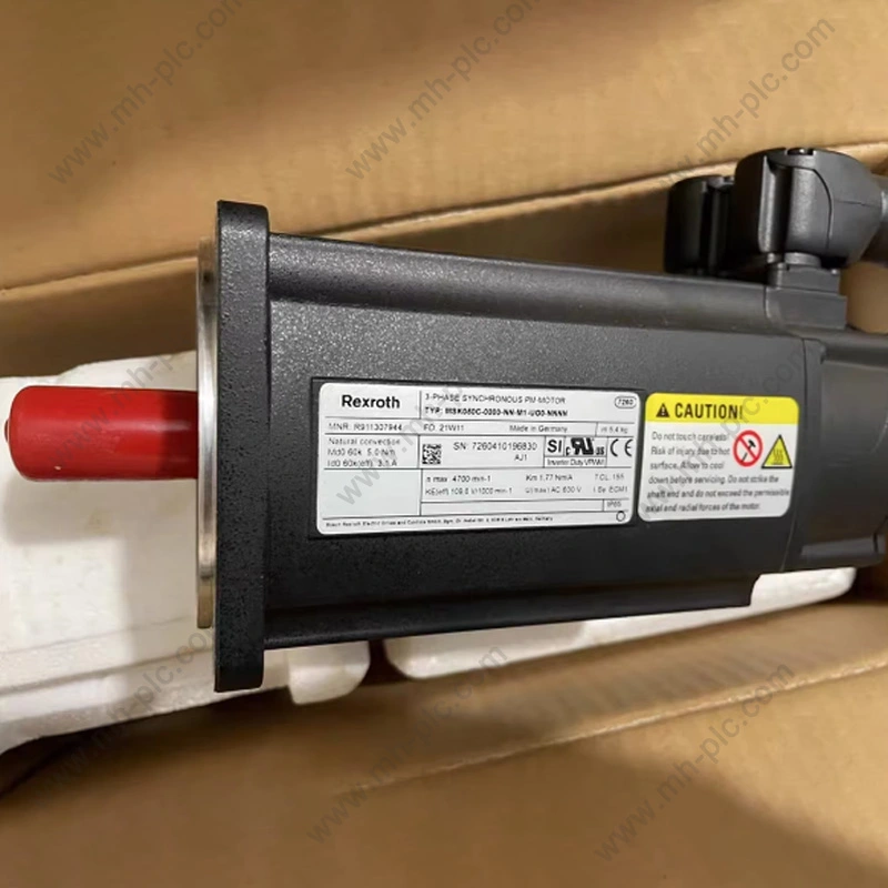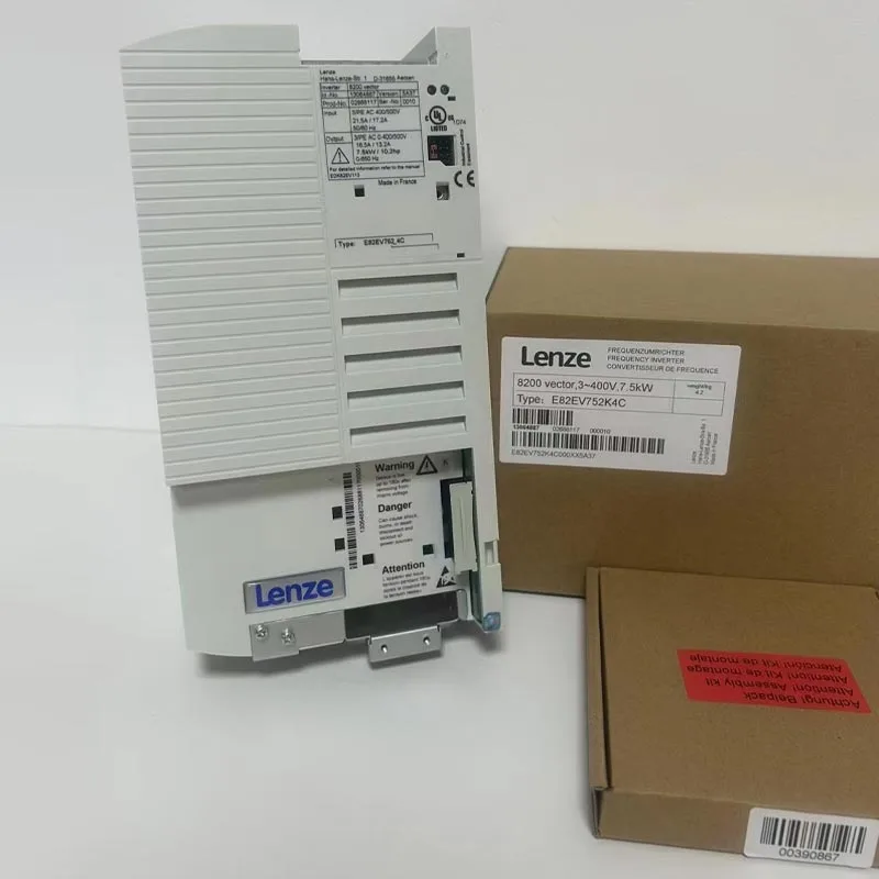

Lenze-inverter solutions are used in industrial motion and motor-control systems where accurate speed regulation, controlled acceleration, deceleration, torque management, and integration with automation equipment are required. Selecting the right inverter is not simply a matter of matching motor power. Engineers also need to consider motor type, supply voltage, output current, control mode, load characteristics, braking requirements, communication architecture, environmental conditions, cabinet constraints, and commissioning procedures. Inverter technology can be applied across conveyors, pumps, fans, packaging equipment, machine tools, material handling systems, and other industrial machinery. The most reliable selection process starts with the machine duty cycle and motor characteristics, then defines the required drive functions, protection, control interfaces, and installation conditions. For buyers sourcing established industrial automation products, accurate model identification and application matching are particularly important because different inverter families can have different interfaces, software functions, dimensions, and installation requirements.
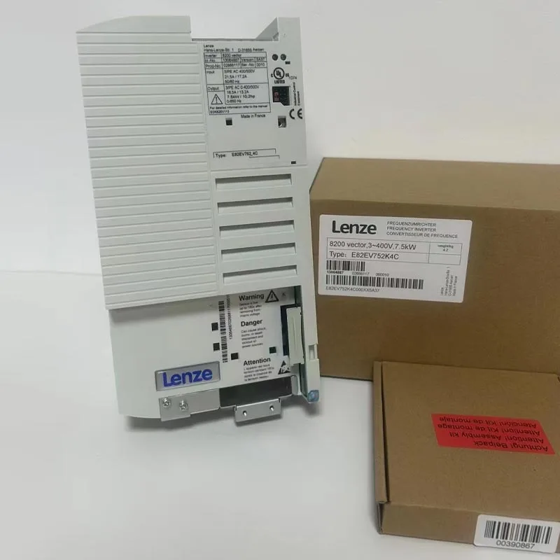
Table of Contents
Click any topic to jump directly to the section.
- 1. Why Is Variable-Speed Motor Control Important in Industrial Equipment?
- 2. How Does an Industrial Frequency Inverter Control a Motor?
- 3. Which Motor and Load Characteristics Should Be Evaluated?
- 4. How Do Control Modes Affect Machine Performance?
- 5. What Do Acceleration, Deceleration, and Braking Functions Do?
- 6. How Does an Inverter Communicate With Automation Systems?
- 7. What Protection Functions Should Be Considered?
- 8. How Do Installation Environment and Cabinet Design Affect Selection?
- 9. How Should Braking, Regeneration, and Deceleration Energy Be Managed?
- 10. Which Industrial Applications Can Use Variable-Speed Drives?
- 11. What Common Selection Mistakes Should Engineers Avoid?
- 12. How Should Existing Systems Be Replaced or Retrofitted?
- 13. What Should a Professional Inverter Specification Include?
- 14. Frequently Asked Questions
Why Is Variable-Speed Motor Control Important in Industrial Equipment?
Many industrial machines do not need a motor to operate at one fixed speed under every condition. Conveyors may need controlled acceleration, pumps may require different flow conditions, fans may respond to changing process demand, and packaging machines often depend on coordinated movement between several axes or stations.
Traditional fixed-speed arrangements can use mechanical methods to adapt machine output, but a variable-frequency drive allows the motor's electrical operating conditions to be controlled directly.
By changing the supplied frequency and voltage according to the selected control strategy, the drive can regulate motor speed and influence torque production. This gives the machine designer a more flexible way to control movement without relying entirely on mechanical transmission methods.
The practical benefit is not simply “changing speed.” Controlled acceleration can reduce mechanical shock. Controlled deceleration can reduce sudden loading on couplings and belts. Adjustable speed can allow a process to operate at the required production condition rather than forcing the motor to run continuously at one fixed point.
Allows motor speed to be adjusted according to machine requirements and process conditions.
Provides a defined ramp from standstill to operating speed, reducing abrupt mechanical loading.
Allows the machine to slow down according to a defined profile rather than stopping abruptly.
Provides a control interface that can connect motor operation to PLCs, HMIs, sensors, and supervisory systems.
Why different machines need different drive behavior
A conveyor carrying a stable load behaves differently from a hoist, extruder, centrifugal fan, or high-inertia machine. Each load creates a different torque-speed requirement.
Some equipment needs high starting torque. Some requires relatively low torque at low speed. Some must accelerate a large rotating mass and then decelerate it repeatedly.
These differences affect the appropriate inverter rating and control strategy.
Speed control and process stability
In industrial automation, speed is often directly related to process quality. Conveyor speed influences spacing. Pump speed influences flow. Fan speed influences air volume. Roller speed influences material handling.
A drive can therefore become part of the process-control loop rather than simply being a motor accessory.
Why motor control should begin with the machine
The first question should not be “Which inverter has the right kW rating?” The better question is “What does the machine require from the motor?”
The answer should include start-stop frequency, continuous operating speed, peak torque demand, acceleration time, deceleration time, load inertia, ambient temperature, and communication requirements.
How Does an Industrial Frequency Inverter Control a Motor?
An industrial inverter converts incoming electrical power into a controlled output suitable for the connected motor. In a conventional AC drive, this process generally involves rectification, DC-link energy storage, and controlled switching through an inverter stage.
Rectifier stage
For a typical AC drive, the incoming AC supply is first converted into DC. The rectifier stage establishes the DC bus used by the downstream switching circuit.
The rectifier configuration depends on the drive architecture and supply arrangement.
DC link
The DC link acts as the intermediate energy section between the input rectifier and the output inverter stage. Capacitors and other components help stabilize the DC voltage and support the switching process.
Inverter stage
The inverter stage uses semiconductor switches to convert DC-link power into a controlled three-phase or other appropriate output. By adjusting switching patterns, the drive controls the voltage and frequency applied to the motor.
Output frequency
Motor speed in an AC induction motor is related to electrical frequency and the motor's number of poles. Changing the output frequency therefore changes the motor's operating speed.
The relationship is not completely direct because slip and load conditions also affect actual motor speed.
Voltage control
The drive also controls motor voltage. Voltage and frequency must be coordinated to establish the desired magnetic flux conditions in the motor.
| Drive Stage | Main Function | Key Consideration |
|---|---|---|
| Input rectifier | Converts AC supply to DC | Supply voltage and input configuration |
| DC link | Provides intermediate DC energy | DC voltage, ripple, capacitance, thermal conditions |
| Inverter bridge | Creates controlled motor output | Switching devices, current capacity, control algorithm |
| Control processor | Calculates switching and motor-control commands | Control mode, feedback, software functions |
| Protection system | Monitors abnormal electrical conditions | Current, voltage, temperature, fault logic |
PWM switching
Pulse-width modulation is commonly used to synthesize the desired motor waveform. The semiconductor switches turn on and off at a controlled frequency, producing a pulse pattern whose effective voltage and frequency can be regulated.
The switching pattern is managed by the drive's control processor.
Motor feedback
Some applications operate without a physical motor encoder. The drive estimates motor behavior from electrical measurements and its control algorithm.
Other applications require encoder feedback when greater speed or position control is needed.
Open-loop and closed-loop operation
Open-loop control does not use a physical speed feedback device. Closed-loop control uses feedback from an encoder or another sensor to improve regulation.
The appropriate approach depends on required accuracy, dynamic response, motor type, and machine process.
The drive is therefore a power-electronics system combined with a control system. The quality of motor performance depends on both the electrical power stage and the control algorithm.
Which Motor and Load Characteristics Should Be Evaluated?
The motor and load define the conditions under which the drive must operate. Correct sizing therefore requires more information than the motor nameplate power alone.
Motor type
Common industrial applications can involve asynchronous induction motors, permanent-magnet motors, synchronous motors, or other motor technologies.
The drive must support the selected motor type and its corresponding control method.
Motor voltage
The motor nameplate voltage needs to correspond to the drive output and electrical system. A mismatch can create incorrect operating conditions.
Motor current
Motor current is particularly important because the drive output stage is generally selected according to current capability as well as power class.
Two motors with the same nominal power can have different rated currents depending on voltage, efficiency, power factor, and motor design.
Base frequency
The motor's rated frequency establishes an important reference point for drive programming. The relationship between voltage and frequency below the base point influences available torque.
Load torque
Torque requirements can be divided broadly into constant-torque and variable-torque behavior, though real machines may be more complex.
Conveyors, hoists, mixers, and extruders often require substantial torque over a broad speed range. Fans and centrifugal pumps can behave differently because their torque requirement changes strongly with speed.
Inertia
Load inertia affects acceleration and deceleration. Large rotating masses require more torque and more time to change speed.
| Motor or Load Parameter | Why It Matters | Selection Impact |
|---|---|---|
| Motor voltage | Defines electrical compatibility | Drive input and output configuration |
| Rated current | Defines motor electrical demand | Drive current rating |
| Motor frequency | Defines operating reference point | Frequency and voltage setup |
| Starting torque | Defines startup requirement | Drive overload and control mode |
| Load inertia | Influences acceleration and deceleration | Ramp settings and braking arrangement |
| Operating speed range | Defines required motor control range | Drive algorithm and motor cooling consideration |
Starting conditions
A conveyor with a heavily loaded belt may require significant starting torque. A fan may have very different startup behavior. A machine tool spindle can require rapid acceleration and precise speed regulation.
The drive needs to be matched to the actual startup condition rather than the average running condition.
Overload requirements
Some applications require short periods of current above the motor's continuous rating. The drive must provide an appropriate overload capability for the specified duration.
Overload data should be interpreted carefully because different drive families can define overload ratings differently.
Motor cooling at low speed
Standard self-cooled motors use an attached fan whose cooling capability decreases at low motor speed. If the machine needs high torque continuously at low speed, additional motor cooling may be necessary.
Nameplate data is essential
- Rated voltage: Confirm the motor's specified operating voltage.
- Rated current: Use the motor current when comparing drive output ratings.
- Rated frequency: Confirm the nominal frequency for the motor.
- Rated speed: Use the nameplate speed as a reference for commissioning.
- Power factor: Consider the motor's electrical operating characteristics.
- Motor connection: Verify the star or delta configuration where applicable.
How Do Control Modes Affect Machine Performance?
Different applications require different levels of motor-control precision. A simple conveyor may not need the same control strategy as a high-performance positioning machine.
V/f control
Voltage-to-frequency control is one of the simplest drive-control approaches. The drive maintains a defined relationship between output voltage and frequency.
This mode can be suitable for relatively simple speed-control applications where high dynamic torque performance is not required.
Sensorless vector control
Sensorless vector control estimates motor behavior and controls flux and torque more independently than basic V/f control.
It can provide better low-speed torque control and dynamic response without requiring an encoder in many applications.
Closed-loop vector control
Closed-loop control uses feedback from an encoder or another sensor. This can improve speed regulation and dynamic response, particularly in applications where speed accuracy and load disturbance response are important.
Position control
Some drive platforms can support positioning functions through integrated motion-control features or coordinated communication with a higher-level controller.
Whether a drive alone can perform the required positioning depends on the specific product and application architecture.
| Control Mode | Typical Character | Potential Application |
|---|---|---|
| V/f | Simple voltage-frequency relationship | Fans, pumps, basic conveyors |
| Sensorless vector | Improved torque and speed control without encoder | Conveyors, mixers, general machinery |
| Closed-loop vector | Feedback-based speed regulation | High-performance speed applications |
| Position control | Coordinated position or motion functions | Motion-intensive machinery |
Why control mode changes machine behavior
Suppose a conveyor suddenly receives a heavier load. With simple control, motor speed may drop more noticeably. A vector-control strategy can respond more aggressively by adjusting the motor's torque-producing current.
The actual behavior depends on the drive tuning, motor model, control settings, and load conditions.
Motor identification
Some drive systems perform motor identification or autotuning. This process measures or estimates motor parameters so that the control algorithm can create a more accurate internal motor model.
The correct commissioning procedure depends on the drive platform and motor type.
Acceleration response
High dynamic performance is not always beneficial. A packaging machine may need rapid acceleration, while a long conveyor may need a smoother profile to avoid belt tension changes.
The control mode should therefore be chosen according to process behavior rather than simply because it offers more features.
What Do Acceleration, Deceleration, and Braking Functions Do?
Acceleration and deceleration settings determine how quickly the motor changes speed. These functions directly affect machine mechanics and the electrical behavior of the drive.
Acceleration ramp
An acceleration ramp gradually increases the command frequency rather than jumping immediately to the target value.
This reduces sudden torque changes and can protect belts, couplings, chains, gears, and other transmission components.
Deceleration ramp
A deceleration ramp gradually reduces motor speed. However, reducing speed can cause the motor to return mechanical energy into the electrical system.
This regenerated energy can increase the DC-link voltage inside the drive.
Braking resistor
When regenerative energy needs to be dissipated, a braking resistor can convert the electrical energy into heat. The drive's braking transistor and resistor selection need to match the application's energy and duty cycle.
DC injection braking
Some drives can inject DC current into the motor to create a braking effect during certain stopping conditions. The function is application-specific and should be configured according to the drive instructions.
Coasting stop
A coast stop removes drive torque and allows the motor and machine to slow naturally. This is useful where a controlled electrical deceleration is not required.
| Stopping Method | Motor Behavior | Typical Use |
|---|---|---|
| Ramp stop | Frequency decreases according to a defined time | General controlled stopping |
| Coast stop | Motor loses drive torque and slows naturally | Low-inertia or non-critical stops |
| Braking resistor | Regenerative energy is dissipated as heat | High-inertia or rapid deceleration |
| DC braking | DC excitation creates a braking effect | Selected stopping and holding applications |
High-inertia applications
Fans, centrifuges, large rollers, flywheels, and similar machinery can store substantial kinetic energy. If the system tries to stop too quickly, that energy can cause the DC-link voltage to rise.
The drive may therefore enter a protective state unless appropriate braking management is provided.
Braking resistor selection
Brake resistor selection depends on resistance value, power rating, pulse duration, duty cycle, drive compatibility, and thermal installation conditions.
A resistor that is electrically compatible for one short event may be unsuitable for repeated braking cycles.
Regenerative systems
Some applications benefit from regenerative drives that return braking energy to the AC supply rather than dissipating it through a resistor.
This architecture is more complex and is normally selected where the application has significant regenerative operation.
How Does an Inverter Communicate With Automation Systems?
Modern industrial drives often operate as nodes within a larger automation system. The drive may receive speed commands from a PLC, exchange status information with an HMI, send alarms to a supervisory controller, or participate in coordinated motion.
Digital inputs and outputs
Basic control can be implemented through digital inputs for start, stop, forward, reverse, reset, or other commands.
Digital outputs can report conditions such as running status, fault status, or speed-related states.
Analog inputs and outputs
Analog signals can represent speed references, process values, or other continuously variable commands. A common arrangement uses a 0–10 V or 4–20 mA signal depending on the control system.
Industrial communication networks
More advanced installations use industrial communication networks to exchange control and diagnostic information digitally.
Depending on the drive family and configuration, interfaces can include fieldbus and industrial Ethernet technologies.
Parameter access
Communication can also provide access to operating parameters, fault history, status words, monitoring values, and diagnostic information.
| Interface | Typical Function | Application |
|---|---|---|
| Digital input | Discrete control command | Start, stop, reset, direction |
| Digital output | Discrete status indication | Running, fault, ready state |
| Analog input | Continuous process or speed reference | Speed command, pressure reference |
| Analog output | Continuous monitoring signal | Speed or current feedback |
| Industrial network | Digital control and diagnostics | PLC integration and machine coordination |
PLC integration
The PLC may send a speed reference and control word while reading actual speed, output current, status, and fault information from the drive.
This digital approach reduces the need for large numbers of hardwired control signals and can provide greater diagnostic visibility.
HMI and operator interaction
An HMI can display drive status and operating values, while allowing authorized personnel to change selected parameters or operating commands.
Critical parameters should be protected from unauthorized modification.
Network architecture
When several drives operate in one machine, the communication network should be planned carefully. Device addressing, cable routing, termination, update rate, control latency, and fault behavior all influence system reliability.
Remote diagnostics
Modern automation architectures increasingly use remote diagnostic functions. Drive alarms and operating data can help maintenance teams identify problems without immediately removing the equipment from service.
What Protection Functions Should Be Considered?
A variable-speed drive operates between the electrical supply and the motor, so it needs protection at both the power-electronics level and the motor-control level.
Overcurrent protection
Excessive current can result from mechanical overload, short circuit, motor faults, incorrect motor parameters, or sudden load changes.
The drive monitors output current and can respond according to its protection strategy.
Overvoltage protection
DC-link voltage can rise because of supply disturbances or regenerative energy during deceleration. The drive can trigger an overvoltage response when the DC-link exceeds its permitted range.
Undervoltage protection
Low input voltage can affect drive operation and motor performance. The drive monitors its DC-link and input conditions and can respond according to its protection logic.
Overtemperature protection
Power semiconductors, heat sinks, cooling fans, and other components produce heat during operation. Temperature sensors can monitor critical areas and initiate a protective response when limits are exceeded.
Motor overload
Motor thermal behavior depends on current, speed, cooling, and operating duty. Drive-based electronic overload protection can use motor current and configured parameters to estimate thermal load.
Earth-fault and output protection
The drive can monitor abnormal current conditions and detect certain output faults. External protection devices remain important, because drive protection does not replace correctly designed upstream protection.
| Protection Function | Possible Cause | Drive Response |
|---|---|---|
| Overcurrent | Overload, short circuit, acceleration demand | Alarm, current limiting, or trip |
| Overvoltage | Regeneration or supply disturbance | Trip, deceleration control, or other protective action |
| Undervoltage | Supply dip or interruption | Alarm, controlled stop, or trip |
| Overtemperature | High load, high ambient, cooling failure | Alarm or protective trip |
| Motor overload | Excessive sustained motor load | Thermal protection or trip |
| Output fault | Motor cable or motor fault | Protective shutdown |
Protective settings need correct motor data
Protection algorithms often depend on motor current, power, voltage, frequency, thermal characteristics, or configured operating limits.
Incorrect motor data can therefore affect both performance and protection behavior.
External protection remains necessary
A drive's internal protection functions do not remove the need for properly selected upstream circuit breakers, fuses, disconnects, grounding, and installation practices.
The complete electrical system needs coordinated protection.
Safe shutdown
Machine-level safety may require controlled torque removal, safety inputs, emergency-stop circuits, interlocks, or dedicated safety-rated functions.
Safety should be designed around the machinery risk assessment rather than relying solely on a standard start/stop input.
How Do Installation Environment and Cabinet Design Affect Selection?
Electrical performance depends partly on how the inverter is installed. The same drive can behave differently in a small sealed cabinet and a well-ventilated control panel.
Ambient temperature
Power semiconductors generate heat, and the ambient temperature determines how effectively the drive can dissipate it.
High ambient temperature may require current derating or additional cooling depending on the product specification.
Ventilation
Cabinet airflow should allow heat to move away from the drive. Blocked vents, inadequate fan capacity, or poor cabinet arrangement can raise internal temperature.
Mounting clearance
Drives require defined clearance around ventilation openings and heat-generating surfaces. The exact distances depend on the product design.
Altitude
At higher altitude, air density decreases, which can affect cooling performance. Some drive installations require derating above specified elevations.
Dust and contamination
Industrial environments can contain conductive dust, textile fibers, oil mist, moisture, or chemical contaminants. Enclosure protection and maintenance requirements should reflect the site conditions.
| Installation Condition | Potential Effect | Design Response |
|---|---|---|
| High ambient temperature | Reduced cooling margin | Thermal evaluation and possible derating |
| Restricted airflow | Heat accumulation | Improve cabinet ventilation |
| High altitude | Reduced air cooling capability | Follow altitude-related derating requirements |
| Dust | Contamination of cooling paths | Suitable enclosure and maintenance plan |
| Moisture | Electrical and corrosion risk | Appropriate environmental protection |
| High switching frequency | Additional losses and EMI | Correct parameter and cable design |
EMC considerations
High-frequency switching creates electromagnetic emissions. Motor cables, grounding, shielding, filters, and cabinet construction can influence electromagnetic compatibility.
Long motor cables may require special consideration because cable capacitance can affect the output circuit.
Motor cable length
The maximum permitted motor cable length depends on the drive design, switching characteristics, motor insulation, cable construction, and any output filter or reactor.
This information should be checked against the product documentation before installation.
Heat dissipation inside the cabinet
It is important to account for the heat generated not only by the drive but also by contactors, power supplies, braking resistors, PLCs, transformers, and other components.
The total thermal load determines whether the cabinet requires fans, air conditioning, or another cooling strategy.
Electrical spacing and wiring
Power wiring and control wiring should be routed appropriately. Separating sensitive communication and analog wiring from high-current switching paths can reduce interference.
How Should Braking, Regeneration, and Deceleration Energy Be Managed?
When an electric motor decelerates, the rotating system does not instantly lose its kinetic energy. That energy has to go somewhere. Depending on the drive architecture, it can be dissipated as heat or returned to the electrical network.
Where regenerative energy comes from
Regeneration commonly occurs when the load drives the motor faster than the commanded electrical speed. High-inertia deceleration and lowering loads are typical examples.
The motor then behaves temporarily as a generator, sending electrical energy back toward the drive's DC link.
DC-link voltage rise
Without a suitable energy-management path, regenerative energy raises the DC-link voltage. If the voltage exceeds the drive's operating limit, an overvoltage trip can occur.
Braking resistor
A braking resistor provides a controlled path for the regenerated energy. The braking circuit switches the resistor into operation when the DC-link voltage reaches the relevant threshold.
Regenerative braking
Regenerative drive systems can return energy to the AC supply. This is useful where regeneration occurs frequently or where braking energy represents a substantial part of the machine's operation.
| Energy Management Method | Basic Principle | Typical Application Condition |
|---|---|---|
| Long deceleration ramp | Reduces regenerative power by extending stop time | Machines that can tolerate slower stopping |
| Braking resistor | Converts regenerative energy into heat | Repeated or rapid deceleration |
| Regenerative drive | Returns energy to AC supply | Frequent or substantial regenerative operation |
| Mechanical brake | Uses physical friction to stop or hold the load | Hoists, safety holding, stationary load conditions |
Hoisting applications
Hoists and lifting systems require special attention because a suspended load can drive the motor during lowering. Electrical regeneration and mechanical holding are separate considerations.
A mechanical brake may be required to hold the load when the motor is stopped.
High-inertia machinery
Centrifuges, large fans, rollers, and flywheel-driven equipment can store significant mechanical energy.
Attempting to stop such a system rapidly may exceed the drive's braking capability unless a suitable energy-management system is installed.
Brake resistor thermal design
Braking resistors can become hot during operation and need appropriate ventilation and physical separation from heat-sensitive components.
The resistor's duty cycle should be calculated from the actual machine operating pattern.
Which Industrial Applications Can Use Variable-Speed Drives?
Variable-frequency drives are used across many industrial sectors because different machines require controlled motor speed and torque.
Speed control, controlled acceleration, direction control, and coordination with upstream or downstream machinery.
Adjustable motor speed for process flow control, pressure management, and soft starting.
Variable-speed airflow control and smooth acceleration for ventilation and process systems.
Controlled speed, repeatable acceleration, communication with PLCs, and coordination across machine sections.
Start-stop control, synchronized movement, braking, and precise conveyor speed management.
Speed and torque control for mixers, rollers, extruders, winding equipment, and similar industrial machines.
Conveyor systems
Conveyors frequently require smooth acceleration and deceleration. Sudden torque changes can cause belt slip, product instability, mechanical shock, or unnecessary wear.
When multiple conveyors operate together, speed references can be coordinated through the PLC or network.
Pumps
Pump applications often require speed variation according to a process condition. A drive can receive a reference from a pressure sensor, flow controller, or PLC and adjust motor speed accordingly.
Selection still requires attention to pump type and load behavior because not all pumps have identical torque characteristics.
Fans
Fans can have strongly speed-dependent torque characteristics. Variable-speed control can therefore provide a flexible method of adjusting airflow.
Fan motor applications should also consider minimum speed, motor cooling, and the operating range of the connected fan.
Packaging machines
Packaging equipment can include several motors operating in coordination. Drives may need fast response, repeatable speed control, communication with the machine controller, and precise acceleration profiles.
Winding and unwinding systems
Winding machinery can require coordinated speed and torque control as the roll diameter changes. Tension control may involve feedback sensors and more advanced control strategies.
Mixers and agitators
Mixers can present changing torque demand as product viscosity and process conditions vary. High starting torque and overload capability can therefore be significant selection criteria.
Machine tools
Machine tools can place greater emphasis on dynamic response and speed accuracy. The drive technology may need to integrate with more sophisticated motion-control architectures.
| Application | Typical Drive Requirement | Important Selection Detail |
|---|---|---|
| Conveyor | Controlled acceleration and speed | Starting torque and braking |
| Pump | Variable speed | Flow, pressure, motor cooling |
| Fan | Variable speed | Load curve and minimum speed |
| Packaging machine | Fast and repeatable control | PLC communication and response |
| Mixer | High starting and overload capability | Torque profile and process variation |
| Winding machine | Speed and torque coordination | Feedback and tension-control architecture |
These applications demonstrate why the same inverter rating cannot be assumed to fit every machine. The drive needs to be matched to the mechanical load, control strategy, and operating cycle.
What Common Selection Mistakes Should Engineers Avoid?
The most common drive-selection mistakes occur when the engineer looks at the motor's nominal power and stops there. A technically correct selection requires a broader review.
- Sizing only by kW: Motor current and application overload requirements may be more important than nominal power.
- Ignoring load torque: A constant-torque load can require a different drive selection from a variable-torque load.
- Ignoring starting conditions: Heavy startup loads can require additional current capability.
- Ignoring braking: High-inertia or lowering loads can create significant regenerative energy.
- Ignoring ambient temperature: High temperatures can require drive derating.
- Ignoring motor cable length: Long cables can affect insulation stress and electromagnetic behavior.
- Choosing the wrong communication interface: The drive must match the PLC and network architecture.
- Ignoring motor cooling: Continuous high torque at low speed can cause motor overheating.
- Using incorrect motor parameters: Poor commissioning data can affect control and protection.
- Ignoring replacement compatibility: A physically similar drive may not have equivalent terminals, dimensions, software functions, or parameter structures.
The power-only problem
Two motors rated at the same power can have different rated currents and different torque characteristics. The drive should therefore be selected using the motor nameplate and actual load profile.
The constant-torque mistake
A conveyor, mixer, or extruder may demand high torque throughout the speed range. Selecting a drive intended primarily for variable-torque loads may not provide the required overload performance.
The braking-afterthought problem
If a machine needs rapid deceleration, braking requirements should be calculated before the drive is ordered. Adding braking hardware later can create panel and thermal-layout problems.
The cooling-afterthought problem
Drive and motor cooling are connected but not identical. A drive can operate within its own thermal limits while the motor overheats at low speed because its shaft-mounted fan is rotating too slowly.
The communication mismatch problem
A machine may use a specific industrial network. Choosing a drive without confirming the required communication option can force unnecessary hardware changes later.
The replacement-equals-equivalent problem
When replacing an older inverter, the new unit should not be selected solely from the old power rating. Engineers should compare voltage class, current, control mode, terminals, dimensions, braking method, communication, safety functions, software, and motor compatibility.
How Should Existing Systems Be Replaced or Retrofitted?
Replacing an inverter in an existing machine requires more than comparing two catalog numbers. The new drive must integrate into the existing electrical, mechanical, control, and safety architecture.
Confirm the existing motor
Start by checking the motor nameplate and actual operating conditions. Motors may have been replaced during the machine's life, so the installed motor should be verified rather than relying entirely on old documentation.
Record existing parameters
Important parameters can include motor voltage, current, frequency, speed, acceleration time, deceleration time, minimum frequency, maximum frequency, control mode, and protection settings.
Check physical dimensions
A replacement drive with the correct electrical rating may still fail the retrofit because the cabinet space is different.
Mounting holes, cable entry, ventilation, terminal position, and heat dissipation should be checked before removal of the existing unit.
Check input and output wiring
Confirm incoming supply arrangement, motor terminals, control wiring, relay contacts, analog signals, digital signals, and communication cables.
Check communication
If the existing drive communicates with a PLC or supervisory system, identify the protocol and required data map before replacement.
Review safety functions
Modern drives may offer safety-related functions that the original drive did not have. The retrofit should assess how the new safety functions interact with the machine safety architecture.
| Retrofit Area | What to Verify | Possible Problem if Ignored |
|---|---|---|
| Motor | Nameplate and operating data | Incorrect current or control settings |
| Cabinet | Dimensions and ventilation | Mounting or overheating problems |
| Wiring | Power and control terminals | Rewiring delays or incorrect connections |
| Communication | Protocol, addressing, data mapping | PLC integration failure |
| Braking | Resistor, braking transistor, stopping time | Overvoltage during deceleration |
| Safety | Emergency stop and safe-torque functions | Incompatible safety architecture |
Parameter conversion
Different drive families organize parameters differently. Even when the replacement product offers the same functional settings, parameter numbers and naming can be different.
A structured parameter-conversion list can reduce commissioning time and prevent accidental omission of important settings.
Motor autotuning
After installation, an autotune or motor-identification routine may be required depending on the selected control mode.
The motor must be in a suitable condition before the procedure begins.
Test sequence after replacement
- Verify wiring: Check incoming power, motor connections, control wiring, grounding, and communication connections.
- Enter motor data: Match the configured values to the actual motor nameplate.
- Check control mode: Confirm the operating strategy required by the machine.
- Test at low speed: Confirm direction, current, vibration, and basic mechanical behavior.
- Test acceleration: Verify the ramp and torque response under representative load.
- Test deceleration: Confirm DC-link behavior and braking performance.
- Test communication: Verify PLC commands, status feedback, alarms, and network data.
- Verify protection: Check configured limits and fault responses according to the commissioning procedure.
What Should a Professional Inverter Specification Include?
A professional specification gives the supplier and engineering team enough information to identify the correct product configuration without relying on assumptions.
| Specification Area | Information to Define | Why It Matters |
|---|---|---|
| Application | Conveyor, pump, fan, mixer, packaging, machine tool, etc. | Determines control and load characteristics |
| Motor type | Induction, permanent magnet, synchronous, or defined type | Determines control compatibility |
| Motor voltage | Rated motor voltage | Ensures electrical compatibility |
| Motor current | Rated current in amperes | Supports accurate drive sizing |
| Motor power | Rated kW or HP | Provides a basic sizing reference |
| Speed range | Minimum, normal, and maximum operating speed | Determines control requirements |
| Overload | Required overload current and duration | Matches drive capacity to the machine duty |
| Braking | Stop time, inertia, resistor or regenerative requirements | Determines energy-management architecture |
| Communication | PLC protocol and required data | Ensures automation integration |
| Environment | Temperature, altitude, humidity, dust | Determines installation suitability |
| Cabinet | Available dimensions and cooling method | Confirms physical installation |
| Safety | Required safety functions and interfaces | Aligns drive functions with machine safety |
Start with the machine application
Identify what the motor is driving and describe the mechanical load. The same motor rating can serve radically different applications.
Provide complete motor nameplate information
Include motor voltage, current, frequency, rated speed, power, connection arrangement, and motor type whenever available.
Define the operating range
State minimum speed, normal speed, maximum speed, start frequency, stop frequency, and the amount of time the machine spends at different operating points.
Define overload and peak torque
If the machine has heavy starting, impact loads, or short periods of elevated torque, these conditions should be stated clearly.
Define braking
Specify the desired stopping time, load inertia, braking frequency, and whether the application requires a resistor, regenerative system, or mechanical brake.
Define control architecture
State whether the machine uses local controls, digital I/O, analog references, PLC communication, industrial Ethernet, or a higher-level motion platform.
Define environmental conditions
Ambient temperature, enclosure temperature, humidity, altitude, dust, and other environmental factors can affect the permissible operating range.
Define physical constraints
For panel installation, provide available width, height, depth, cable routing, ventilation space, and mounting-hole limitations.
Model identification is especially important for branded industrial products
When sourcing an established branded inverter, the exact model code matters. Small changes in a model suffix can correspond to different voltage classes, ratings, options, communication interfaces, or hardware generations.
Buyers should therefore provide the complete existing nameplate or product code when replacing an installed unit.
- Identify the machine: Define the driven equipment, operating cycle, and process requirements.
- Record motor data: Confirm power, current, voltage, frequency, speed, and motor type.
- Define load behavior: Identify constant torque, variable torque, high inertia, or other load characteristics.
- Define control: Specify speed range, control mode, feedback, and response requirements.
- Define braking: Establish deceleration time and regenerative conditions.
- Define communication: Identify PLC protocol, interface, and required status data.
- Review environment: Confirm temperature, altitude, dust, humidity, and cooling conditions.
- Review physical fit: Confirm drive dimensions, mounting, terminals, and cable access.
- Confirm model: Verify the complete part number, voltage class, current rating, and available options.
- Plan commissioning: Prepare motor parameters, control logic, test procedures, and backup settings.
What should a buyer provide when requesting a supplier quotation?
- Complete motor nameplate: Include power, voltage, current, frequency, and speed.
- Existing inverter model: Provide the full model number for replacement applications.
- Machine description: Explain the application and load characteristics.
- Input supply: State supply voltage, phase, and frequency.
- Control requirement: Specify local control, I/O, analog, or communication requirements.
- Braking condition: State whether rapid stopping or regenerative operation is required.
- Installation condition: Provide cabinet dimensions and environmental information where relevant.
This level of information makes it easier for a supplier to identify a technically compatible product instead of relying on a generic power-range recommendation.
For replacement and sourcing projects, accurate model identification is particularly valuable because branded industrial automation products are often available in several closely related variants.
Frequently Asked Questions
What is the main function of a Lenze inverter?
Its primary role is to regulate motor operation by controlling electrical output conditions such as frequency and voltage. Depending on the specific product family, the inverter can also provide ramp control, torque control, braking functions, diagnostics, communication, and automation integration.
Can an inverter control motor speed?
Yes. By adjusting the output frequency and corresponding voltage according to the selected control strategy, an AC drive can regulate motor speed within its specified operating range.
Should an inverter be selected according to motor power or current?
Both matter, but rated motor current is especially important because drive output stages are designed around current capability. The application overload requirement should also be considered because machines with the same motor power can place very different demands on the drive.
What is V/f control?
V/f control maintains a defined relationship between output voltage and frequency. It is a relatively simple control method and can be suitable for applications where basic speed control is sufficient.
What is sensorless vector control?
Sensorless vector control estimates motor behavior and regulates flux and torque without requiring a physical speed encoder in many applications. It can provide improved low-speed and dynamic performance compared with basic V/f control.
When is encoder feedback useful?
Encoder feedback can be useful when the machine requires tighter speed regulation, improved dynamic response, or feedback-based control. The need depends on the application and the capabilities of the selected drive family.
What causes an inverter to trip on overvoltage during stopping?
Rapid deceleration of a high-inertia load can return energy from the motor to the drive DC link, causing the DC-link voltage to rise. A longer deceleration ramp, braking resistor, regenerative system, or another appropriate braking method may be required depending on the application.
Does every application need a braking resistor?
No. The need depends on load inertia, stopping time, operating cycle, speed, and regenerative energy. Low-inertia applications with slow deceleration may not require one, while high-inertia or frequently stopping machines may require braking hardware.
Can an inverter control a pump?
Yes. Variable-speed drives are commonly used with pumps to adjust motor speed according to process requirements. The exact control strategy should consider pump type, flow conditions, minimum speed, motor cooling, and the process-control system.
Can an inverter control a conveyor?
Yes. Conveyor applications often use drives for speed control, smooth acceleration, controlled stopping, forward and reverse operation, and coordination with other machine sections.
Why is motor current important when choosing a drive?
Drive output components are designed for specific current levels. Two motors with the same power rating can have different rated currents, so the drive should be matched to the actual motor nameplate current and the application overload requirement.
Can an inverter operate a motor at low speed continuously?
It depends on the motor and application. A standard self-cooled motor can lose cooling capacity at low speed. If high torque is required continuously at low speed, an independent cooling fan or another motor-cooling arrangement may be necessary.
How does an inverter communicate with a PLC?
Depending on the product and configuration, communication can use digital I/O, analog signals, fieldbus networks, or industrial Ethernet. The drive can exchange commands, status information, operating values, alarms, and diagnostic data with the PLC.
Can a drive be connected to an HMI?
Yes. An HMI can display drive parameters, operating states, alarms, and selected process values. It may also provide authorized parameter and command functions depending on the automation architecture.
What environmental conditions should be checked?
Important conditions include ambient temperature, cabinet temperature, altitude, humidity, dust, oil mist, vibration, ventilation, and other contamination. These factors can influence drive capacity and installation suitability.
Why does motor cable length matter?
Long motor cables increase cable capacitance and can influence output waveform behavior and insulation stress. The permissible cable length should be checked against the drive's technical documentation and any required output filters or reactors.
Can a different inverter replace an existing Lenze drive?
A replacement from another product family may be possible, but it should be treated as an engineering substitution rather than a direct assumption of equivalence. Voltage, current, control mode, braking, dimensions, terminals, communication, software, safety functions, and motor compatibility all need to be compared.
What should be checked when replacing an existing drive?
Check the complete existing model number, motor data, supply voltage, current rating, cabinet dimensions, terminals, braking system, control wiring, PLC communication, safety interfaces, cable length, and existing parameter settings.
What is overload capability in a drive?
Overload capability indicates how much current the drive can provide above its continuous rating for a defined duration. The exact overload specification varies by product and application category, so the required machine duty must be compared with the manufacturer's rating.
Why can a drive overheat even when the motor is not fully loaded?
Drive temperature depends on switching losses, ambient temperature, enclosure ventilation, carrier frequency, installation spacing, and other conditions. A drive can operate near a thermal limit because of poor cooling even when motor load is moderate.
Can the same drive be used for both pumps and conveyors?
Possibly, if the drive supports both applications and the ratings are appropriate. However, the control strategy, overload requirement, braking, and load characteristics can differ substantially between a pump and conveyor, so the exact configuration should be checked.
What information should a supplier receive for product matching?
Useful information includes the complete inverter model, motor nameplate data, supply voltage, application type, required speed range, overload condition, braking requirements, communication protocol, cabinet dimensions, and installation environment.
Is a drive supplier the same as a drive manufacturer?
No. A supplier or distributor can source, identify, match, and provide branded industrial drives without being the original manufacturer. For procurement projects, the supplier's ability to identify the correct model and configuration is particularly important.
How Can Better Inverter Selection Improve Industrial Motor Control?
Industrial motor control works best when the drive is treated as part of the entire machine rather than as an isolated electrical component. The motor, mechanical load, control architecture, braking system, cabinet, PLC, communication network, and protection devices all influence the required configuration.
The first step is to understand the machine. A conveyor, pump, fan, mixer, packaging machine, winding system, and machine tool can all require different motor behavior even when their motors have similar nominal power ratings.
Motor data provides the electrical foundation. Rated voltage, current, frequency, speed, motor type, and connection must be known. Load characteristics then add the next layer: starting torque, continuous torque, inertia, acceleration, deceleration, speed range, and overload duty.
The control method should be selected from these requirements. Basic V/f control can be sufficient for straightforward applications, while sensorless or closed-loop vector control can provide better torque and speed performance when the machine demands it.
Braking requires separate attention. High-inertia machines and lifting systems can regenerate significant energy during deceleration. The correct solution may involve a longer stopping ramp, braking resistor, regenerative system, or mechanical brake depending on the application.
Communication has also become a central part of modern industrial drive integration. Digital I/O, analog signals, fieldbus networks, and industrial Ethernet can connect the drive to a PLC and broader automation system. Correct protocol and data mapping should therefore be defined before procurement.
Environmental design is equally important. Ambient temperature, cabinet ventilation, altitude, dust, humidity, motor cable length, EMC, and physical mounting constraints can all affect successful operation.
For procurement and replacement work, model identification deserves special attention. A branded industrial drive may be offered in several closely related versions with different voltage classes, current capabilities, interfaces, dimensions, or options. The complete model code should therefore be verified before the product is selected.
When sourcing a lenze-inverter solution, the strongest procurement approach is to match the exact model and application requirements first, then verify motor compatibility, control functions, communication, braking, installation conditions, and documentation.
Need Help Matching a Lenze Drive to Your Application?
Mao Hui supplies branded industrial automation products and supports model identification, application matching, replacement sourcing, technical specification checks, and configuration review for motor-control projects. For product details and application requirements, contact us.